04. Train crossing (part 2) - Automated barrier
Hi,
So, you successfully finished your LED Traffic Lights, nice!
Lets move up a scale and get into the automated barrier.
This second part is more complex yet still doable.
# Train crossing (part 2) - Automated barrier


 |
| from Busch |
 |
| from Modelismo Artesanal |
From finished product I could get wight into business. But first the material I needed.
Material:
 |
| 9g servos |
* 2x micro servos - don't buy continuous rotating servo, just standard 180º servos. I bough SG90 servos but latter I found that actually the MG90S all metal gears is way more stable.
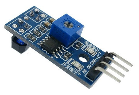 |
| iR sensor |
* 3x iR sensors - found that TCRT5000 fitted my design.
 |
| wire Jumpers |
* wire jumpers female to female for pyboard interconnection
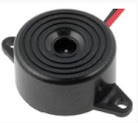 |
| buzzer |
* 1x buzzer - found these 1.5V to 30Vdc 12mA from Loudity on my local Electronic store pretty cool. Buy 2x just in case.
 |
| K-Line sheet |
* 1x sheet of K-line - 3mm will be fine for the electronics apparatus. Also used 3mm hard cardboard on a latter model.
Step 1 - Build the Electronics support.
Cut a square piece of K-line sheet, the the size of the crossing. This will be used to attach and connect all the electronics below the train crossing.
Make space to include one or two tracks as desired. Remember if you use 2x tracks you will need to increase your iR sensors from 3x to 4x (code is ready for up to 4x iR sensors)
Cut the holes for the servo actuator and iR sensor. Test with servos more less in place directly bellow the barrier actuator but slight deviated with the barrier pendulum.
When testing the servo actuator I found that best moves slight diagonally from barrier pendulum, not straight in line, since the barrier moves diagonally just like the servo arm.
 |
| K-line for Electronics support with holes needed |

To interconnect the Servo to the barrier pendulum I used a paper clip that I bended and cut to my desire.

For this you need to connect all Electronics to the pyboard with the SW loaded in the Micropython board and all the apparatus in the K-line.
Obs. You can use previously adapted USB charger to power your MicroPython project.
Connect everything like bellow:

to test use the iR sensor, or press the 'USR' switch on the pyboard
The remaining two or three iR sensor you will install on the remaining track to detect train before entering and after leaving either side of the St. Andrews Crossing. Pyboard has one dedicated entry for each iR sensor, you can connect up to four.
 |
| Apparatus under Train Crossing |
* * *
Pyboard Software:
Revert to Micro Python SW section on this blog to understand the Python code or simply download latest version below for your St. Andrews Crossing.
* * *
Video from the final product
MB
--> 04/2024
Design flaws and corrections
After intensive testing some corrections to HW and SW were needed.
HW
- replaced original servos for a better all metal gear. Original ones had some type of glitch and unstable movement. So... replaced the plastic SG90 by all metal gear MG90S, witch is a better upgraded version of the SG90. Best found that Servos operate at 6Vdc, so I bought a L7806CV voltage regulators for micropython supply.
  |
| L7806CV MG90S |
- The iR sensors were connected to 3.3V from micropython as stated in vendor documentation. 'Kinda' burned a couple with 5V until I realize the mistake. So... Re-wiring was needed, and diagram above was updated.
SW
- reshaped SW to allow 4x iR sensors individual input and not in series connection. Now, all iR sensors have a separate input on micropython. Also added an external config.txt file for servo adjustment without the need to tamper with main code.
 |
| config.txt |
download and upload these two files below to pyboard


Comments
Post a Comment